Auto Mains (Utility) Failure Control Modules

DSE7320 MKII

Auto Mains (Utility) Failure Control Module
The DSE7320 MKII is a powerful, new generation Auto Mains (Utility) Failure genset control module with a highly sophisticated level of new features and functions, presented in the usual DSE user-friendly format. Suitable for a wide variety of single, diesel or gas Gen-set applications. 


Featuring a new Dual Core main processor and extended memory, the module provides faster and more powerful processing power, returning faster operational responses on intensive applications and increased functionality, with data logging facility. 

Monitoring an extensive number of engine parameters, the module will display warnings, shutdown and engine status information on the back-lit LCD screen, illuminated LED's, remote PC's and via SMS text alerts (with external communication device).

To view UL Certification click here.
Read More

OVERALL SIZE
245 mm x 184 mm x 51 mm (9.6" x 7.2" x 2.0")

PANEL CUTOUT SIZE
220 mm x 160 mm (8.7" x 6.3")

MAXIMUM PANEL THICKNESS
8.0 mm (0.3")

PRODUCT VARIANTS
7320-03 - 7320 MKII Auto Mains (Utility) Failure Control Module

Request a Quote

e -
Please select a product
Please enter a quantity
e +

add another product

Please enter your title
Please enter your first name
Please enter your surname
Please enter your company name
Please select your country
Please enter a delivery County/State
Please enter your email
Please enter your mobile number
Webform URL: Website Option: Webform: Named Distributor: Distributor's Email: Named Reseller: Reseller's Email:


l

Product Highlights

Key Features & Benefits

Key Features

Key Benefits

Configurable power-up mode.
Choose to power up the module in stop / manual / auto mode.
MPU fail delay.
If an MPU failure is detected the alarm can be delayed to allow for transient in the signal.
Enhanced graphical user interface.
Major design changes added to V7 to make the GUI easier to understand.
Drag and drop advanced PLC editor.
Powerful PLC editor functionality as standard.
MSC ID within PLC GenComm override.
PLC logic can be created to change the MSC ID to avoid having to use DSE Configuration Suite on-site.
Closed transition support with check sync.
The load can be transferred from generator to mains (utility) or mains (utility) to generator without a break in the power supply.
Mains (utility) and generator breaker alarms.
Required to ensure the closed transition function operates correctly.
Open transition support with check sync.
The phase angle between generator and mains (utility) voltages is check to be in sync before the open transition limiting potential damage to rotating machinery.
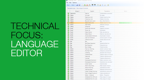
Supports 7 languages.
English and 6 alternative languages can be stored in the control module.
Crank disconnect on generator voltage.
Provides the ability to crank disconnect on generator voltage.
Oil pressure disconnect delay.
Delays the crank disconnect on oil pressure to compensate for cold oil.
DSE25XX MKII supported over DSENet®.
Increases the number of supported DSE25XX MKII to two by allowing a single DSE25XX MKII to communicate over DSENet®.
Charge alternator disable functionality.
Charge alternator support can be disabled. This removes all related information from the front panel editor and SCADA.
3 digital input functions added to allow ECU specific operations.
Provides additional flexibility by allowing users to turn on additional engine functionality on supported electronic engines.
Supports escape mode.
Allows an engine to be run when it has received a shutdown command related to efficiency limits.
Configurable icon screens.
Icon layout on module screens can be configured to suit individual applications.
Comprehensive monitoring of the mains (utility) supply and auto changeover.
A genset controller and ATS in one compact housing.
4-line back-lit LCD text display
Provides comprehensive and clear indication of operation and parameters.
Five key menu navigation
Provides convenient and flexible navigation of parameters.
Support for up to three remote display units
Provides the option to mimic the main control module up to 1.2 km.
Configurable inputs (8)
Provides multiple installation options.
Configurable analogue / digital inputs (6)
Provides flexibility for multiple installation options.
Configurable outputs (8)
Provides multiple installation options.
Tier 4 CAN engine support.
Ensures the control module can be used with the latest in modern electronic engine technology.
Manual fuel pump control.
Allows the fuel tank to be filled to provide reassurance of system operation.
Power monitoring (kW h, kVAr, kv Ah, kV Ar h), reverse power protection, kW overload protection.
Provides clear accurate power measurement information.
Mains monitoring and automatic start and changeover to generator power in the event of a mains (utility) out of limits or failure.
Provides the reassurance of back up power being available in an emergency.
Configurable CT positioning.
The CT can be placed in the Generator output to provide current readings and protection or alternatively placed in the main load output to provided generator and mains (utility) readings and protection.
Data logging facility
Provides current and historical status information.
Customisable power up text and images
Company logo can be uploaded to the start up splash screen.
Support for 0-10 V & 4-20mA oil pressure senders.
Provides support for a wide range of sensors and parameters.
Can be configured for use as a remote display module
Single product can be used for dual functionality.
  • Additional Features
  • Voltage measurement.
  • kW overload alarms
  • Exercise timer.
  • Multiple language options.
  •  
  • Configurable timers & alarms.
  • Configurable maintenance alarms (3).
  • Charge alternator failure alarm.
  •  
  • Speed control for speed control enabled electronic engines.
  • Heated Display option

Specification

DC SUPPLY

CONTINUOUS VOLTAGE RATING
8 V to 35 V Continuous
5 V for up to 1 minute

CRANKING DROPOUTS
Able to survive 0 V for 100 mS, providing supply was at least 10 V before dropout and supply recovers to 5 V. This is achieved without the need for internal batteries. LEDs and backlight will not be maintained during cranking. 

MAXIMUM OPERATING CURRENT

510 mA at 12 V, 240 mA at 24 V

MAXIMUM STANDBY CURRENT
330 mA at 12 V, 160 mA at 24 V

CHARGE FAIL/EXCITATION RANGE

0 V to 35 V

GENERATOR & MAINS (UTILITY)

VOLTAGE RANGE
15 V to 415 V AC (Ph to N)
25 V to 719 V AC (Ph to Ph)

FREQUENCY RANGE

3.5 Hz to 75 Hz

MAGNETIC PICK UP

VOLTAGE RANGE
+/- 0.5 V to 70 V

FREQUENCY RANGE

10,000 Hz (max)

Environmental Testing Standards

ELECTRO-MAGNETIC  COMPATIBILITY
BS EN 61000-6-2
EMC Generic Immunity Standard for the Industrial Environment.
BS EN 61000-6-4
EMC Generic Emission Standard for the Industrial Environment.

ELECTRICAL SAFETY
BS EN 60950
Safety of Information Technology Equipment, including Electrical Business Equipment.

TEMPERATURE
BS EN 60068-2-1
Ab/Ae Cold Test -30°C.
BS EN 60068-2-2
Bb/Be Dry Heat +70°C.

VIBRATION
BS EN 60068-2-6
Ten sweeps in each of three major axes.
5 Hz to 8 Hz @ +/-7.5 mm, 8 Hz to 500 Hz @ 2 gn.

HUMIDITY
BS EN 60068-2-30
Db Damp Heat Cyclic 20/55° C @ 95% RH 48 Hours.
BS EN 60068-2-78
Cab Damp Heat Static 40° C @ 93% RH 48 Hours.

SHOCK
BS EN 60068-2-27
Three shocks in each of three major axes 15 gn in 11 ms.

DEGREES OF PROTECTION PROVIDED BY ENCLOSURES
BS EN 60529
IP65 - Front of module when installed into the control panel with the supplied sealing gasket.

Connection Diagram
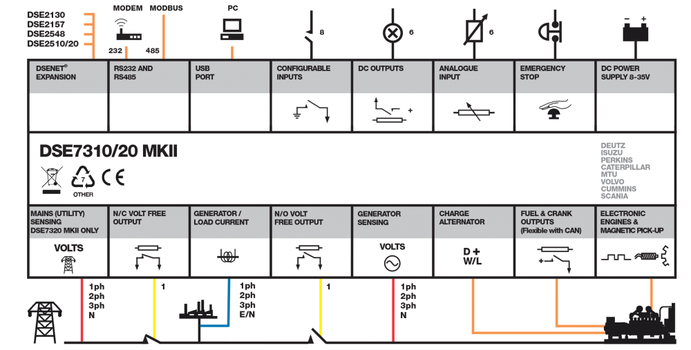
DSE7320 MKII connection diagram

Product Variants

7320-03 - 7320 MKII Auto Mains (Utility) Failure Control Module